Compliant Mechanisms achieve part or all of their motion
from the deflection of their members. Instead of rigid body engineering (i.e.
pins, joints and rigid segments) compliant mechanisms use their deformation to
accomplish the desired motion. Some benefits of this design method include
reduced wear, lower friction, energy storage potential, lower assembly needs.
Examples of compliant mechanisms are a bow, springs, trees, eels and virtually
everything in nature.
One of the key challenges of incorporating compliant
mechanisms into design is the rigorous mathematical sequence to analyze the
design’s performance. Small angle approximations have been developed to
simplify design, but these approximations are not appropriate for the range of
motion found in many compliant mechanisms as they typically fall apart at a few
degrees of deflection. Dr. Howell, Professor of Mechanical Engineering at BYU, teaches
methods to evaluate the behavior of compliant mechanisms. One of his methods
requires many inputs and iterations due to the evaluation of elliptic integrals.
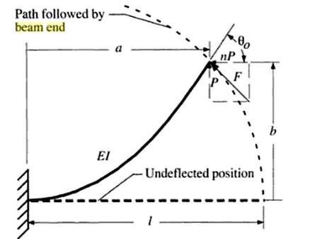
For my project I built a user interface for one specific
design case – a beam cantilevered at one end with an applied force at the
other. An example of this condition would be a thin metal ruler clamped at one
end and a point force applied on the other end. Dr. Howell provided an excel
file with the elliptical integral functions built and I created the user form.
This project enables his students, and others he distributes it to, to better
understand the non-linear behavior of these systems as they change parameters.
It gives them a simple system to improve their intuition. The graphs enable the
user to learn:
- the shape the beam will deflect to subject to the conditions entered,
- the stress profile along the length of the beam and
- the internal moment along the length of the beam.
No comments:
Post a Comment